Woah, this thread is still alive! Yes everyone, this mod is easily doable with only beginner soldering skills. If you've never soldered before practice first by replacing the tact switches and jog wheel of the MPC 1000 because we both know they need to be replaced anyways. Also there is literally 0% chance of bricking your MPC 1000/2500 by doing this mod, although you may brick your "buydisplay" if you connect everything up wrong, but even then that chance is small because these displays are pretty resilient. And as previously stated in this thread, desoldering the old display cable is doable but muuuch harder than you think it will be and not worth the hassle when making a new cable is so incredibly cheap.
I'll try to summarize this mod:
What you will need:
BuyDisplay 240x64 in the color of your choice.
-Do not get the 2x11 pin header soldered onto your display from the factory because you want an IDC connector not a pin header on the display.
-Technically this mod will work with a 240x128 BuyDisplay as well, but it won't come with a fancy casing like the 240x128 screen you can get off mpcstuff
https://www.buydisplay.com/240x64-ra696 ... hic-module20 Position IDC "ribbon/flat" cable-You will need a minimum of 10 inches of cable to do this mod, thus it's worth the extra expense to get a longer ribbon cable just in case you **** up. Buy at least 15-25 inches of cable.
-2.54 pitch cable, 28AWG with a minimum of 20 pins is all that matters. If a cheaper option has more than 20 pins you can always peel off the extra pins from the cable. It doesn't matter if you get either the rainbow colored cable or grey cable with the red line at the bottom.
Here's a cheap 20 inch cable from a quick amazon search that you will need to cut the ends off of (well at least one end, i'm not sure if the female socket will fit on the bottom of the MPC 1000 so i'm just going to assume that we're using a ribbon cable with no sockets)
https://www.amazon.com/BLS-2-54mm-20-Pi ... 714&sr=8-5ConnectorsIDC 2x10 20 Pin IDC Male Plug Connector 2.54mm pitch
https://www.amazon.com/gp/product/B07FD ... UTF8&psc=1IDC 2x10 20 Pin IDC Female Socket Connector 2.54mm pitch
https://www.amazon.com/gp/product/B07DV ... UTF8&psc=1-These suggested amazon links are merely for reference purposes. I'm not saying you should buy from these links or that they are the best deals. They are literally just the first thing I found while looking for the connectors and cables to write up this post and are intended to merely give you an idea of what the cables and connectors look like
-With that said, I highly highly suggest you buy extra connectors just in case you **** up. Just like with buying extra cable, it's better to have more than not enough when working on an electronics project. I personally bought a pack of 10 connectors for both the male and female ends and while making my cable I broke three connectors just trying to crimp them onto the wire. Crimping by hand/pliers is a simple process, but more difficult than you would think! Buy extra just in case!
ToolsYou will also need a soldering iron (obviously), black electrical tape, wire stripper and a multimeter to check your connections if you're not confident with soldering. You will also need some small wire to cut into three parts to jump the pins. You can recycle this wire from broken electronics you have lying around or you can buy some basic 22 AWG wire or something. It doesn't really matter the AWG size just as long as it's not too big to fit.
First things first is to make the cable.

1. Cut roughly 10 inches of IDC cable.
2. Get the male connector and crimp it on left end of the cable. The orientation of the male connector is the same no matter which way you turn it so it doesn't matter how you crimp it. For continuity with the old cable keep the red stripe at the bottom.
3. Crimp the female socket on the right end.
Make sure the arrow on the female connector is facing the outside of the cable and that the male and female connectors are both facing downwards Pic related. The arrow is on the bottom part of the connector facing the outside of the cable.


--Tips on crimping--
As you'll see crimping is harder than it looks. I suggest you start by pushing down on the top part of the crimp in order to make an indent. Then take off the top part or header or whatever and get a small flathead screwdriver and push in on the cable from the outside ends and then the middle section between the pins. Keep cycling between using the detachable header part and using a screwdriver until it clicks into place and is locked.
--For the curious--
Yes, your observations are correct. The male pin connector has the pins inverted. Pin 2 is connected to Wire 1, Pin 1 is connected to Wire 2 and etc. It's suppose to be like that, don't worry about it. Pic related, this orientation of the male pin connector is correct even if it's counter-intuitive.
 Soldering
1. Use the electrical tape and make sure the male connector is flush against the BuyDisplay PCB. Then just solder all the pins. Easier said than done for a beginner, but very doable. Don't worry about putting too much heat on the PCB, it can take wayy more heat than you think. These things are not as fragile as you would imagine.

2. Now solder a small wire from pin 9 to pin 20. It's important to do this wire connection first because soldering it last will make it harder to solder due to less room.
3. Then solder Pin 21 to Pin 3
4. Then Solder Pin 22 to Pin 2
*remember to tin your wires first, it makes the job much easier

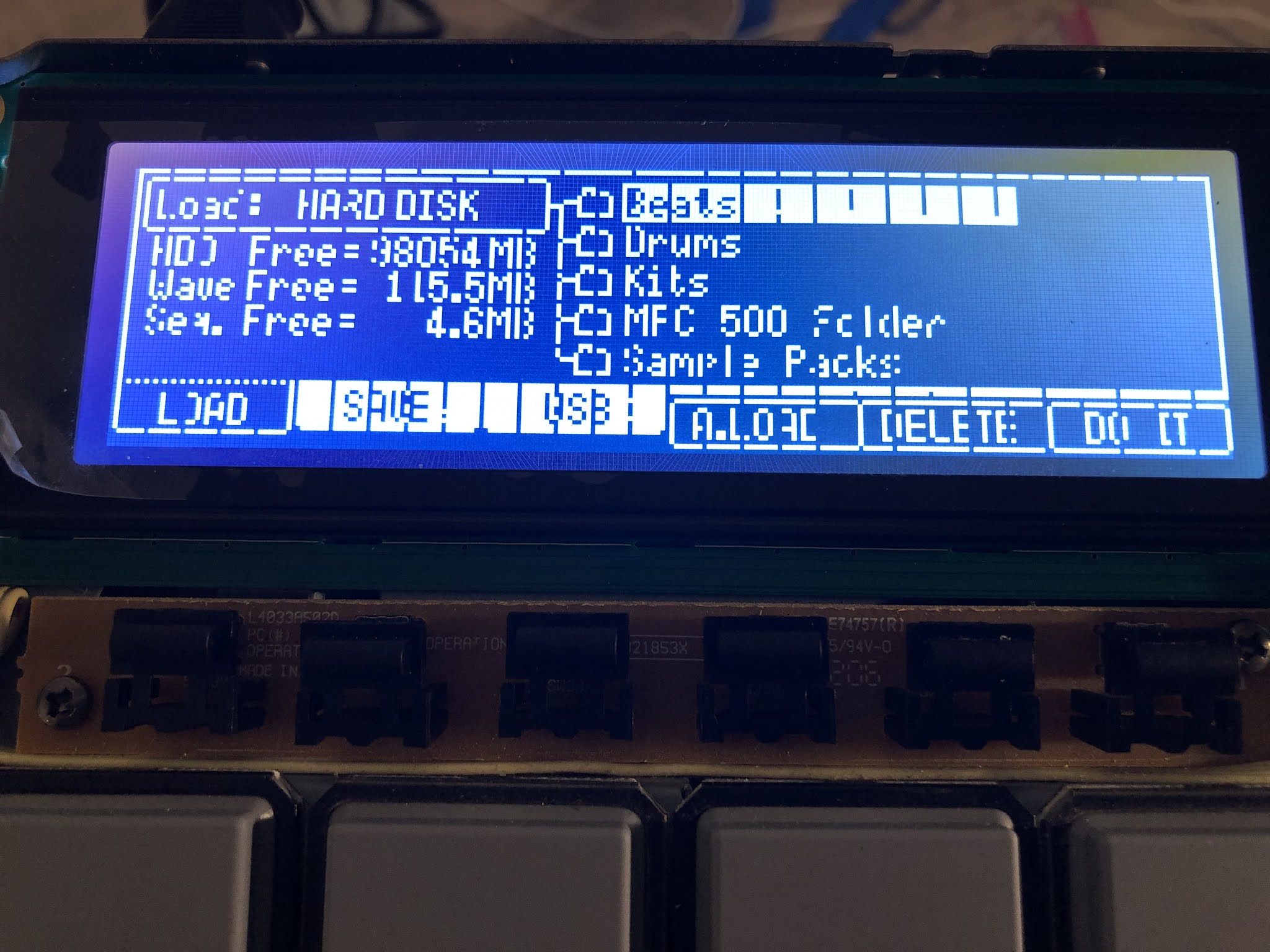
Now you're done. Just flip over the MPC and test it out by plugging in the screen. Make sure the arrow on the female connector matches with Pin 1 on the MPC 1000 PCB

*It's worth noting that a lot of light leaks from the sides of the screen. Use the black electrical tape to tape over the sides that leak light.