

Sense-A wrote:The one I installed into my Kurzweil K2000 has a resistor jumping from pin 3 to pin 21. pin 22 is not used.
I looked at the pinout for the linked replacement T6963 and the LCD pinout in the MPC1000 service manual. Most pins appear to match up. However...
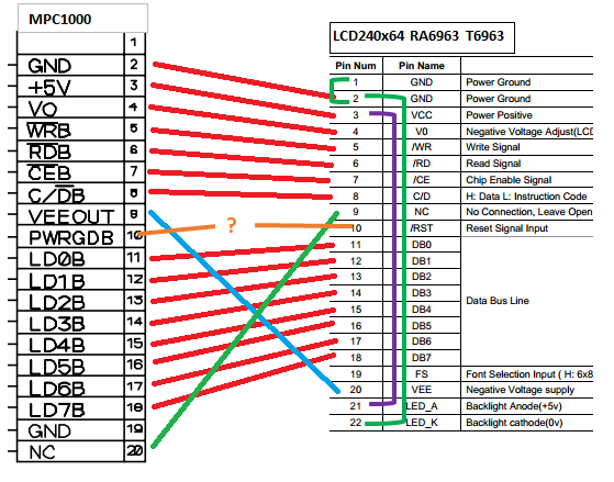
The MPC 1000 LCD has 20 pins. The replacement has 22 pins.
Pin 9 from the mpc1000 must go to pin 20 on the T6963. Just how Slump drew it.
Slump left pins 10 disconnected on both sides. I'm not sure if that's okay.
Pin 10 on the T6963 is "Reset Signal" whereas on MPC 1000 it says "PWRGDB"
Also the T6963 has +5V backlight on pin 21 and 0V backlight cathode on pin 22. I'm not sure if these can be left unhooked or not...Although, I found that if I connected the anode pin (LED_A) and logic power pin (VCC) together on the actual display unit, while also connecting the ground (LED_K) to ground, I could get the backlight to light, but it's generally advised against for reasons I'm not sure of. This Is why I ultimately decided to pull a separate 5v for the LED from the power section of the PCB. The problem is the mpc is so much more complex and I don't know if I have the technical know how to find a clean and easily accessible 5v source just to power the backlight's LED. Again, looking at the mpcstuff.com's product photo I can see that the A and K pins on the board have big globs of hot glue on them. Did they just connect the anode (Pin A) to the logic supply voltage (VCC)? Does it actually matter that much to have a clean independent voltage to power the LED?
On the one for my Kurzweil K2000, I think the guy jumped pin 3 (VCC +5V) to pin 21 as you did. But he used a resistor to make the jump, which probably is there for protection and for the same reason you were advised not to use the single source 5V to power both the VCC and backlight without a resistor.
You can probably leave pin 22 not connected (NC).
Too bad Slump hasn't responded. he seemed to be the furthest along and close to getting it working.
I replaced my K2000 keyboard's LCD display. All I did was remove the old LCD screen and place the new compatible LCD screen, which had 22 pins. The additional 2 pins are for backlight LEDs, which you'd just supply 5V DC from power supply.
As far as all the connection goes, it is that simple. No sane LCD manufactures would change PIN outs! Just connect pin to pin (don't leave any pins unsoldered), and provide 5VDC on Pin 21 & 22.

 so when power ups it remains black.