By horisonten
Tue Jun 23, 2020 11:44 am
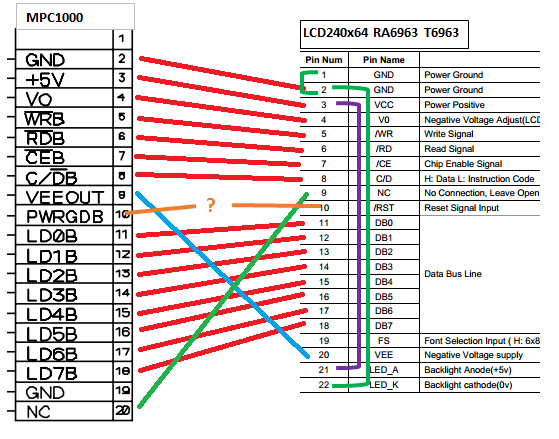
I'm now even more confident that the PWRGDB should be connected to the /RST on the LCD.
I found this in the RAIO-chip manual on the BuyDisplay site.
RST I (Reset Signal)
RST = Low = RA6963 will be reset.
RST = High = Normal mode. RA6963 built-in a Pull-Hi resistor.
And this about usual Power Good implementation:
"The Power Good signal (sometimes called Power_OK or PWR_OK) is a +5 V (nominal) active high signal (with a variation from +2.4 V through +6.0 V generally being considered acceptable) that is supplied to the motherboard when the power supply has passed its internal self-tests and the output voltages have stabilized."
So this should mean that the LCD is in reset state upon Power on of the MPC.
And as soon as the MPC1000 is done with its self-tests the Power Good sends out a High signal to the LCD and it thus enters its normal operation mode.