Support and discussion for all of Akai’s modern standalone MPCs including the MPC X / X SE, MPC Live 1, 2 & 3, MPC One / One+, MPC Key 37/61.
User avatar
By jabberwalky Tue Jun 14, 2022 12:16 pm
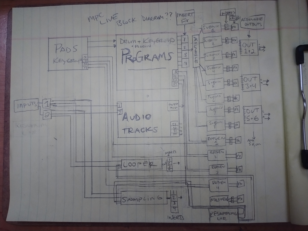
Since some others mentioned in another thread, seems Akai has never released a block diagram of the signal flow. My bad attempt at figuring out how it functions while avoiding doing my job. Maybe someone could improve it. Edit: The pads/keygroups should also have their own 4 insert FX per.

(click the link for full size image)
https://postimg.cc/QBhPCMKw
Image
By c-real Tue Jun 14, 2022 1:10 pm
Hi,
It's a very good initiative. Thanks for your job.
I think you missed the insert FX for the 3 stereo output busses, the metronome, the headphone output, the MIDI/CV/Clip programs. Maybe you could treat and display the Resample module as a common stereo inputs.
The best thing would be a collaborative process ending up with a digital version of the Block Diagram. I'm not good at making these kind of things, but I'm sure someone here is talented for this task.
Cheers,
creal.
User avatar
By jabberwalky Tue Jun 14, 2022 1:14 pm
Oh yes, you're right! This may take a larger sheet of paper. Maybe there a place to make block diagrams online somewhere? I'm not super familiar with them clearly lol.

The resample module is confusing. I'm still trying to figure out where that fits.
By c-real Tue Jun 14, 2022 1:37 pm
You can do it for free with Inkscape (a vector diagram based software). Maybe you should focus solely on audio paths (as you already do) and let the control paths away (CV, MIDI).
Another diagram would be cool for illustrating sequences, tracks, patterns, associated programs. Maybe just a kind of timeline with captions?
You're right. You have to find what's going in/out of the Resample module in order to wire it correctly.

EDIT: in the series of "Akai didn't give enough precisions in their manuals", a few years ago I did a kind of MIDI implementation chart. For the ones who are interested in: https://docs.google.com/spreadsheets/d/ ... =755042769
User avatar
By NearTao Wed Jun 15, 2022 4:53 pm
Looks pretty good... I suspect there might be a way to simplify a point or two, but the way you did it is quite clear.

* Audio Inputs can be 1/2/3/4, as the X does have 2 additional inputs (also with its own mix/cue)...
* USB audio interfaces can change the inputs/outputs a bit
* Maybe I'm wrong, but isn't there also a master output/mixer... or is that really just 1+2 and I need to look at my MPC interface again :D
User avatar
By jabberwalky Wed Jun 15, 2022 5:31 pm
@NearTao : Thanks! Yeah, I think it could be refined for sure. I did forget to make a block for "masters"! but it is essentially just the different output pairs which I put there. It can be changed to other outputs.

I left it as just the stuff Live has since I don't own an X to reference.

Some other weird points that aren't super evident:
- Headphone output only works with Outs 1,2
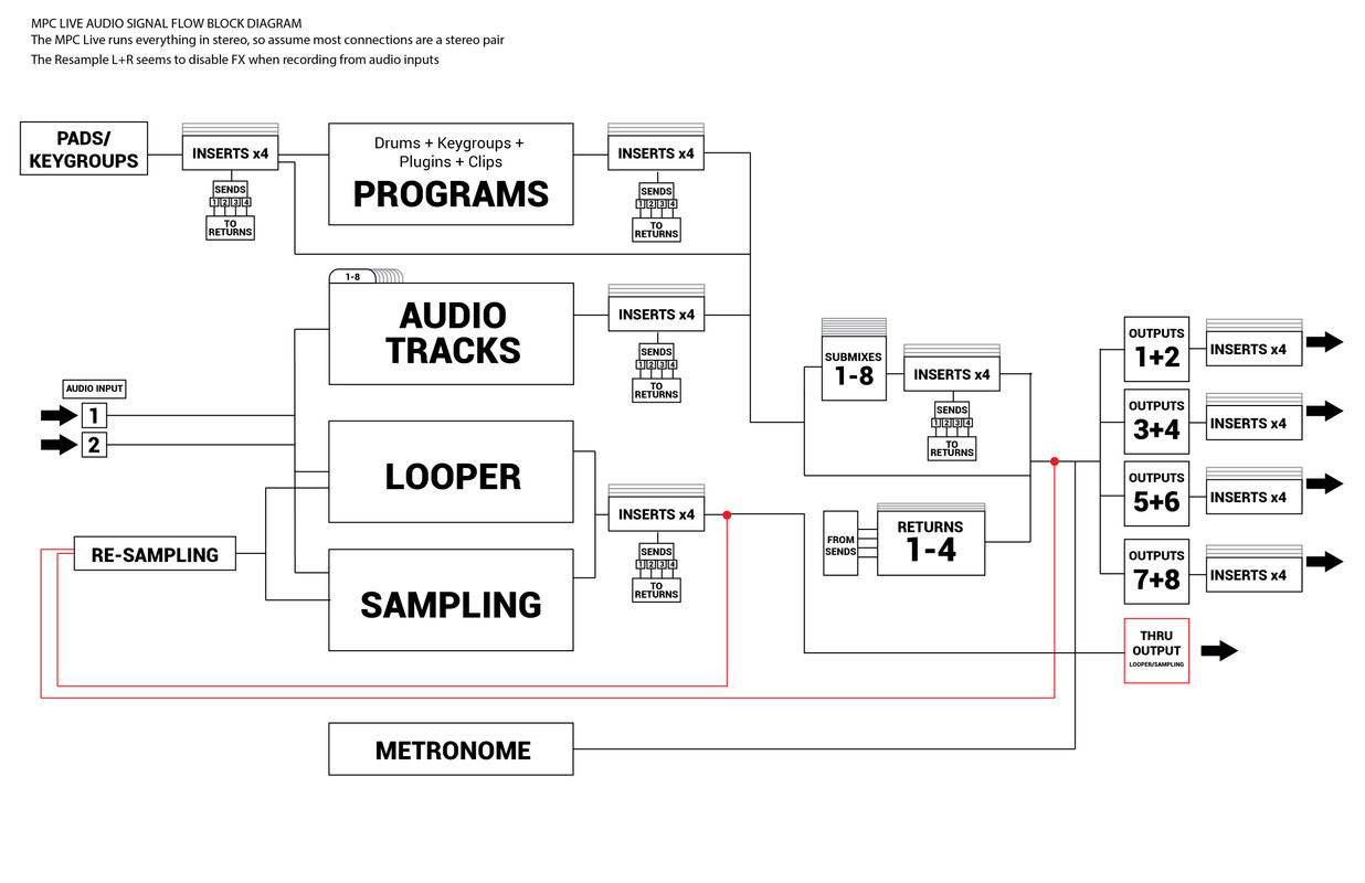
- I was really struggling with the way the re-sampling is routed. I think it's either a glitch, or possibly intentional that it disables FX for audio input, because it seemed to be routed with the red lines in the diagram, which you'd assume would have FX applied to inputs!
- I don't use looper really, but I didn't realize that it shares the same 4 FX slots as the sampler
- Audio routed through sampler/looper don't actually ever hit the master outputs (at least in the mixer), which is odd. No meters are moving when playing something in with monitor "IN". Maybe some kind of feedback would happen.
- You can route individual pads/keygroups to different outputs...which is fine, but wow, can that get confusing when the program is routed somewhere else! Especially when you can still route each pad/kg to a send as well. Curious how people use this flexibility.
- A useful tip for people playing live is you can route metronome to another output, and send that signal into a mixer tape input. With proper setup, you can hear the click in the headphones, but it doesn't send to FOH
By Zack Zerox Thu Jun 16, 2022 6:00 am
It's good to see it laid out clearly. Be great if Akai would release a more detailed & official one which accounts for all the gain stages (velocity response/level in program edit, pad mixer, channel mixer and so on). They must have one!
By KaoticShock Fri Jun 17, 2022 1:28 am
I just read through the entire MPC User Guide from Akai, no signal Flow diagram.

My Roland Fantom X6 has a signal Flow chart and options BUILT-IN to the firmware. HOW? How are products from 2004 still more technologically advanced than these MPC's from 2017???????

Anyway, thanks for the updated PDF version, greatly appreciated.
By c-real Sun Jun 26, 2022 7:22 am
jabberwalky wrote:@NearTao : Thanks! Yeah, I think it could be refined for sure. I did forget to make a block for "masters"! but it is essentially just the different output pairs which I put there. It can be changed to other outputs.

I left it as just the stuff Live has since I don't own an X to reference.

Some other weird points that aren't super evident:
- Headphone output only works with Outs 1,2
- I was really struggling with the way the re-sampling is routed. I think it's either a glitch, or possibly intentional that it disables FX for audio input, because it seemed to be routed with the red lines in the diagram, which you'd assume would have FX applied to inputs!
- I don't use looper really, but I didn't realize that it shares the same 4 FX slots as the sampler
- Audio routed through sampler/looper don't actually ever hit the master outputs (at least in the mixer), which is odd. No meters are moving when playing something in with monitor "IN". Maybe some kind of feedback would happen.
- You can route individual pads/keygroups to different outputs...which is fine, but wow, can that get confusing when the program is routed somewhere else! Especially when you can still route each pad/kg to a send as well. Curious how people use this flexibility.
- A useful tip for people playing live is you can route metronome to another output, and send that signal into a mixer tape input. With proper setup, you can hear the click in the headphones, but it doesn't send to FOH


Hello,

Thank you for redesigning the diagram. It is very useful.

Is there a chance to optimize it a little bit, please? Some insights here:

- drawing the headphone physical output (as triangle, square?) to the extreme right (see below)
- either inverting the "4 inserts" and "Outputs X+Y" blocks, considering "Outputs X+Y" is the physical outputs (not the bus) OR (better in my opinion), just add the physical output pairs to the extreme right, along the headphones output (just for 1+2), as triangles, squares or anything else
- the "through output" is not clear to which physical outputs it goes out. The physical outputs triangles/squares would also help here

Let me know if my English is not clear,

Have a nice day,

creal.